
In this post I share my solution to an internal hacker challenge relating to identifying the UART pins on a VOIP phone and using them to gain root access.
UART (Universal Asynchronous Receiver-Transmitter) is a hardware device that is used for serial communications. It comes in the form of a physical circuit or as a standalone integrated circuit. UART is used to transmit and receive serial data and is very commonly included in the microcontrollers for the purposes of testing.
Figuring out the pinout, baud rate and rooting the device
UART uses two wires to transmit and receive, which connect to Tx and Rx pins. However, UART is very commonly seen in a group of three pins. The third pin in UART is usually the ground pin.
Before you start identifying the baud rate, you need to identify the correct pinout. You can use a multi-meter to do that. First thing we need to do is to identify points of interest. UART usually consists of two pins, so we need to identify where on the board UART could possibly be.
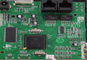
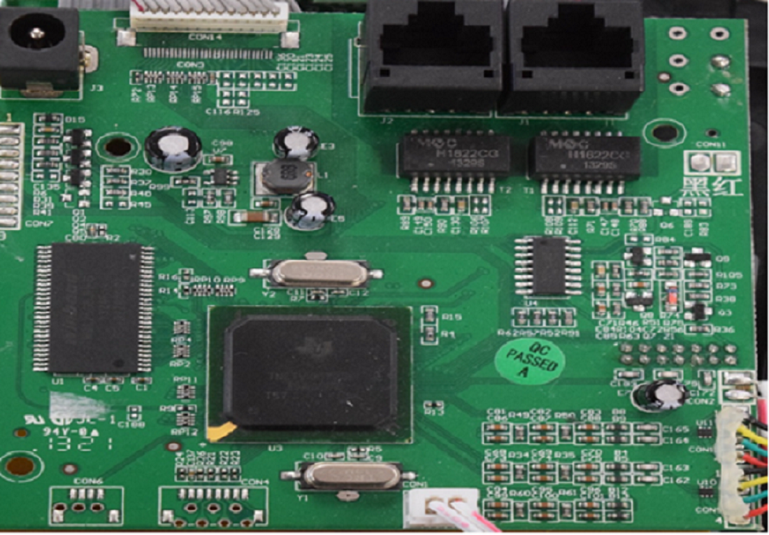
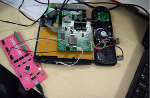
Inside of the Yealink SIP-T20P IP Phone
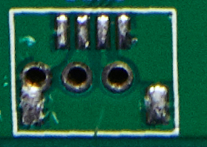
Above is an image of the PCB of a Yealink SIP-T20P IP Phone. We can see that this board contains two sets of pins in the bottom left corner of the board. As we know, UART consists of two pins, so we can safely say that the pins on the left could be what we are looking for:

Points of interest
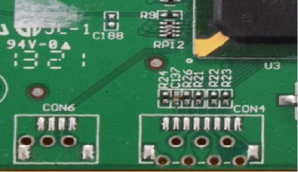
Traces are those lines that go from the microcontroller to the pins. The dark green part is the isolation bit and the part in-between the isolation is where the copper trace runs and connect the pins to the microcontroller.
UART traces
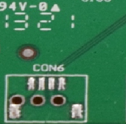
Now that we know where our UART pins are, the next job is to figure out which pins are Ground, Tx and Rx. There are many ways that this can be done. Firstly, we need to identify the Ground pin. In the image below, we can clearly see that the middle pin and right pin are connected to traces, so we can assume that these are the Tx and Rx pins of UART. The Ground pin can be easily identified as it will not have any traces going towards it. In this case, the Ground pin is the pin on the left, as we can clearly see that there is no trace going towards it – it is directly connected to the ground plane.
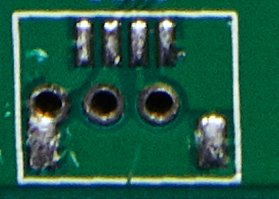
UART pins
Once we have identified the Ground pin, we need to identify the Tx and Rx pins. This can be done in many different ways. One of these ways is very easy, and regards basically guessing the pins. There is a 50/50 chance that you will get it right, so if it does not work the first time, you can just change the pinout and it should work.
Another way of identifying the Tx and Rx pins is to use a specialist tool, such as a JTAGulator. JTGAulator will be able to tell exactly which pin is which.
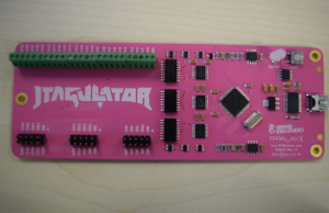

The JTAGulator
Above is a image of a JTAGulator. JTAGulator has a set of connectors which can be used to find out the UART pinout, provide UART pass-through, connect JTAG, etc. In order to use it, we need to connect it to a USB port on our laptop to provide power. Once we do that, we use jump wires to connect the JTAGulator to our UART pins. JTAGulator connectors are all labelled starting from GND (Ground) pin, VADJ pin, and CH (Channel) pins, which range from 0 to 7.
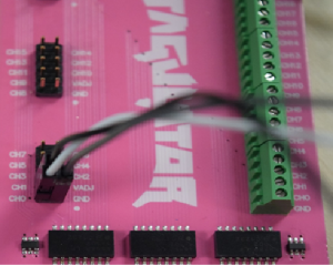

Picture showing The JTAGulator testing pins
In order for the JTAGulator to work, we need to connect the pins correctly, so GND to GND, and Channels 0 and 1 to what we think are the Tx and Rx pins. Once finished, it should look like this:

The JTagulator connected to the UART pins of the IP Phone
Once the wires are connected, we need to find the correct baud rate in order to specify the rate at which bits are transmitted to get a human readable output. If baud rate is mismatched, the data can be either misinterpreted or completely missed. There are many different ways to figure out the Baud Rate of different boards. One way is to basically just guess the baud rate. There are several typically-used baud rates, such as 110, 300, 600, 1200, 2400, 4800, 9600, 14400, 19200, 38400, 57600, 115200, 128000 and 256000 bits per second. Basically, connect the device and try those different baud rates until you get readable output is also a way of figuring out the baud rate.
Another way of figuring out the baud rate is to use an oscilloscope. In order to do that, we need to connect our oscilloscope to the Tx pin and then set our oscilloscope to trigger a pulse. Once this is done, we then measure the time of the shortest pulse and the reciprocal of that pulse is the baud rate. To provide an example, if our shortest pulse is 100µs, then our baud rate will be 1/(100 * 10^-6) = 10,000. As 10,000 is not a real baud rate, we round it to the closest possible baud rate which is 9,600 and there we have our baud rate.
Using JTAGulator is another way of finding out the baud rate and pinout. Once we have the JTAGulator connected to our laptop, we need to communicate with it. JTAGulator is using a USB for power and connection, so we need to be able to achieve serial communication with the device. This can be achieved by using a screen tool on Linux, or putty on Windows. We used Debian, so the tool we used for serial communications was screen. Therefore, in order to establish serial communication, we run the command below:
$ sudo screen /dev/tty.usbserial-AL024BCV 115200
The command above can be used to establish serial communication with our JTAGulator device. The command screen invokes the tool; the next part of it is where we specify the device to connect to – /dev is a directory in Linux where we can find all devices that are currently connected to our machine. A ttyUSB0 is the name of our JTAGulator device and the number after it is the baud rate. The baud rate can be found in the JTAGulator documentation. When we run this command, we will end up with a connection to JTAGulator:
:h
JTAG Commands:
I   Identify JTAG pinout (IDCODE Scan)
B   Identify JTAG pinout (BYPASS Scan)
D   Get Device ID(s)
T   Test BYPASS (TDI to TDO)

UART Commands:
U   Identify UART pinout
P   UART passthrough

General Commands:
V   Set target I/O voltage (1.2V to 3.3V)
R   Read all channels (input)
W   Write all channels (output)
J   Display version information
H   Display available commands
Now that we have established our serial communication with the JTAGulator, the first thing we need to do is to set the I/O voltage. If you try to do anything without setting the I/O voltage first, the device will prompt you to set the voltage. To set the voltage on the JTAGulator, we press V and then Enter. This will prompt us to select a set a voltage ranging from 1.2V to 3.3V. In this case, we have set the voltage to be 3.3V. The voltage needed to transmit data though the pins is usually contained within a datasheet of the device. However, 3.3V is a commonly used voltage in bigger chips. Smaller chips might use a voltage of 1.2V. It is essential to select a correct voltage. If the voltage is too big, it can damage the chip. On the other hand, if the voltage is too low, it can damage the device that is trying to communicate with the chip (in this case, the JTagulator).
:v
Current target I/O voltage: Undefined
Enter new target I/O voltage (1.2 - 3.3, 0 for off): 3.3
New target I/O voltage set: 3.3
Ensure VADJ is NOT connected to target!
:
Once the voltage is set, we can start doing the pinout and baud rate identification. In order to do that, we press U and then enter. The JTAGulator will then prompt us for some information regarding the pinout identification such as:
- Text String to Output – This is the string that will be used to test different baud rates and based on the output we will be able to identify the correct one if the string is outputted the same. In this case, we will be using a string “test”
- Number of Channels – Number of channels is used to determine how many pins we are going to be using for the pinout identification. There is a maximum of 24 channels, 8 on each set of pins on our JTGAulator. In this scenario, we are doing UART which has only three pins and only two that are used for communications, so the number of channels that we are going to need is two. More channels may be required, however, when trying to identify JTAG pinout, for example
:U
Enter text string to output (prefix with \x for hex) [CR]: test
Enter number of channels to use (2 - 24): 2
Ensure connections are on CH1..CH0.
Possible permutations: 2
Press spacebar to begin (any other key to abort)...
Now that we have got our parameters setup, we can start enumeration of the pinout and the baud rate. In order to begin, we need to press the spacebar and the JTAGulator will iterate through possible combinations of the pinout and baud rate:
TXD: 1
RXD: 0
Baud: 1200
Data: ..... [ FF FF FF FF FF ]

TXD: 1
RXD: 0
Baud: 1800
Data: .... [ FF FD FD FD ]

TXD: 1
RXD: 0
Baud: 2400
Data: ... [ FD F5 FD ]

TXD: 1
RXD: 0
Baud: 3600
Data: 9.9 [ 39 FF 39 ]

TXD: 1
RXD: 0
Baud: 4800
Data: .. [ F0 FA ]

TXD: 1
RXD: 0
Baud: 7200
Data: .. [ 8C B0 ]

TXD: 1
RXD: 0
Baud: 9600
Data: .. [ 00 ED ]

TXD: 1
RXD: 0
Baud: 14400
Data: ic.. [ 69 63 D6 F8 ]

TXD: 1
RXD: 0
Baud: 19200
Data: .....f.`..C.... [ A7 B7 15 19 80 66 B0 60 08 F4 43 9D 0E B9 FE ]

TXD: 1
RXD: 0
Baud: 28800
Data: di.. [ 64 69 DE FF ]

TXD: 1
RXD: 0
Baud: 31250
Data: ...x. [ D4 D6 B6 78 F5 ]

TXD: 1
RXD: 0
Baud: 38400
Data: ..... [ B4 E5 B3 1B F9 ]

TXD: 1
RXD: 0
Baud: 57600
Data: test...starting [ 74 65 73 74 0D 0A 0D 73 74 61 72 74 69 6E 67 20 ]

TXD: 1
RXD: 0
Baud: 76800
Data: tt... [ 74 74 82 8E F8 ]

TXD: 1
RXD: 0
Baud: 115200
Data: .....0. [ 80 80 0C 80 80 30 F8 ]

TXD: 1
RXD: 0
Baud: 153600
Data: ... [ F0 F8 FC ]

TXD: 1
RXD: 0
Baud: 230400
Data: .... [ F8 F8 F8 F8 ]

TXD: 1
RXD: 0
Baud: 250000
Data: .... [ F8 00 F0 F8 ]

TXD: 1
RXD: 0
Baud: 307200
Data: ... [ E0 F0 F0 ]
.
UART scan complete!
:
Once we start our iteration, we will see the output of different combinations that the JTAGulator has tested, as in the image above. We will need to go through those and see which one returns the string we have entered as one of our parameters.
TXD: 1
RXD: 0
Baud: 57600
Data: test...starting [ 74 65 73 74 0D 0A 0D 73 74 61 72 74 69 6E 67 20 ]
In the image above, we have located the correct pinout and baud rate for the Yealink SIP-TP20P IP Phone. So now that we have all the information we need, we can use these to correctly connect the pins and establish serial communication. Again, there are many different tools we can use to do that, such as a USB to Serial Adapter, or even JTAGulator. In this example, we will use the JTGAulator to perform something called UART pass-through. In case someone does not have or cannot afford a JTAGulator, there are other, cheaper solutions available (for example, USB to UART bridge modules or the Bus Pirate). These are USB sticks with UART connectors that allow a bi-directional link between USB bus and UART serial bus.
UART Commands:
U Identify UART pinout
P UART passthrough
In order for us to perform a UART pass-through using the JTAGulator, we need to press P and then enter. This will prompt us to give some information which we have collected in the previous task. Once we enter the UART pass-through mode, JTAGulator will ask us for the channel numbers of the Tx and Rx pins. So based on the information we collected, we know that the Tx pin is connected to channel 1 and the Rx pin is connected to channel 0. Once we supply the pin information, we will then be asked to supply the baud rate. As we know from the previous task, the baud rate is 57,600.
:p
Enter new TXD pin [0]: 1
Enter new RXD pin [0]: 0
Enter new baud rate [0]: 57600
Enable local echo? [y/N]:
Entering UART passthrough! Press Ctrl-X to abort...
Once we enter this information, we can establish a UART pass-through. In this particular case, the device does not provide any security measures and as soon as you connect, you get through a booting process. To get to a root shell, the device must not be connected to the network, as right after the DHCP fails, you need to press enter and you get dropped into a root shell.
#
# id
uid=0(root) gid=0(root)
#
In the next part of this series, we will cover how another of the Team tackled the JTAG challenge.