
In my previous post, I worked around the fact that the card reader could only read credit cards – when I wanted to read other types of magstripes. I’d thought at the time that it would theoretically be possible to replace the firmware. In this post I don’t get as far as writing new firmware, but I to present an easy way to download and upload firmware: The ST-Link v2 USB device (hardware) and associated ST-Link Utility (software).
Inspiration
I’d been watching YouTube videos about microcontrollers, when I stumbled across How to Set up the ST-Link v2 Programmer Tutorial for ARM Microcontrollers. I hadn’t come across this method of programming microcontrollers before. Previously, I’d only programmed my Arduino via UART.
I got straight on eBay and bought a programmer from a local supplier, so it would arrive quickly. The same thing is also available for about £2 from China.


ST-Link v2 on eBay
Pinout
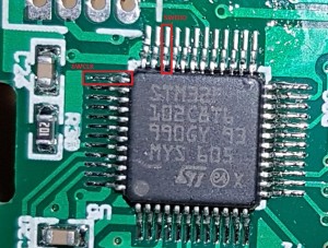
The chip I wanted to program/read was the STM32F102C8 from my cheap magstripe reader:

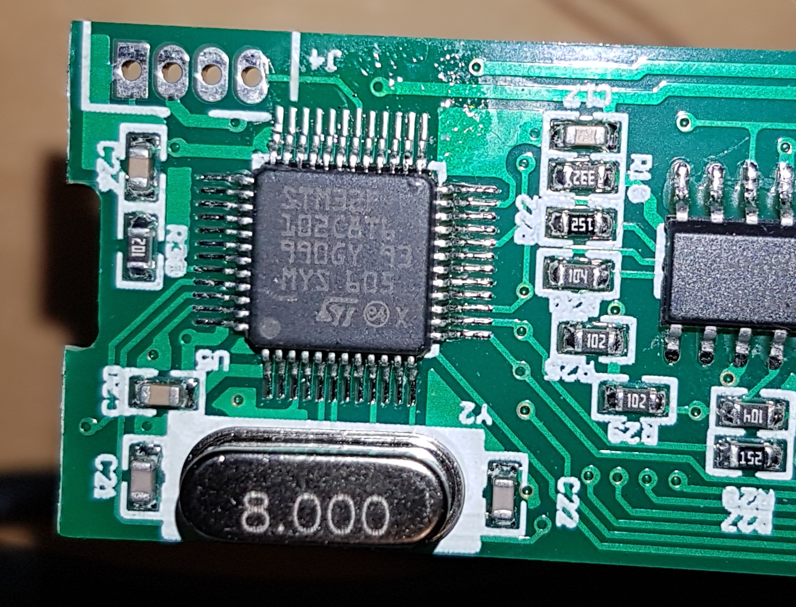
Chip on card reader
The datasheet (pdf) showed the pinout information I needed:
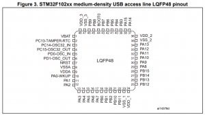

Pinout from STM32 datasheet
The pins I needed to locate were the Serial Wire Debug (SWD) pins. Specifically SWDIO and SWCLK:
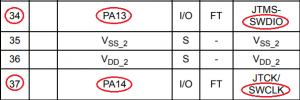
Locations of SWDIO/SWCLK pins
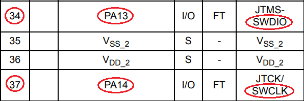
Marking up the previous diagrams, we have identified the pins we need:
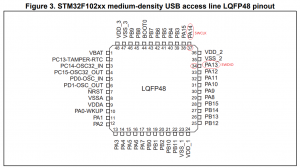
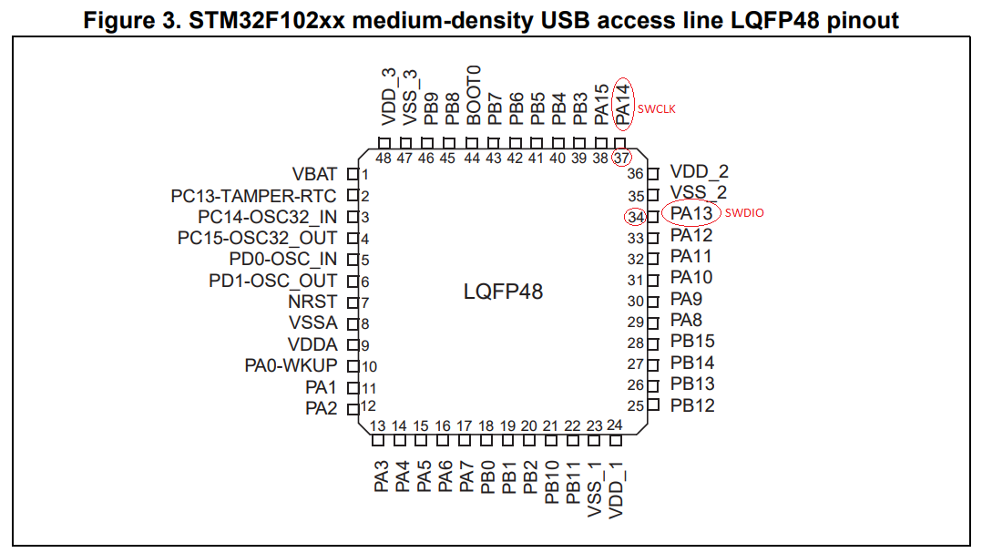
Location of the pins we need

Pin locations marked
In case you’re wondering, if you connect your oscilloscope to the SWDIO and SWCLK pins while the device is powered up, you don’t see any signals. But this doesn’t mean the pins are disabled – as we’ll show below.
Soldering
After successfully soldering some enamelled copper wire to the pins, then almost ripping the pins off accidentally, I used some hot clue as strain relief. The other end of the wire was connected to some 0.1″ headers so I could use dupont cables to connect to the ST-Link.

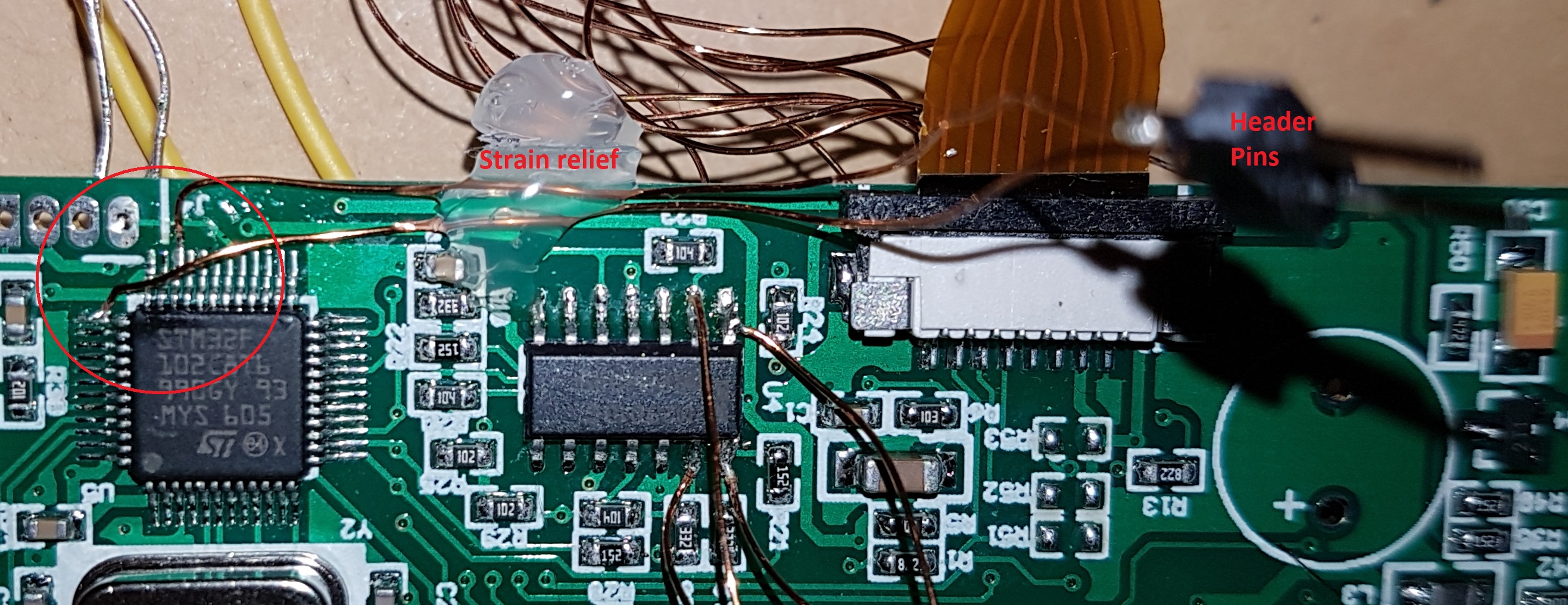
Connections soldered to pins
I was pretty pleased with my soldering as it was the first time I’d soldered to pins with such fine pitch. I found that by tinning the wire very slightly, then resting the wire on the pin as I gently lowered the soldering iron (no solder on the iron), I was able to avoid spreading solder onto the nearby pins.
Connecting to ST-Link
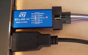
Using dupont connectors we need to make 3 connections between the ST-Link device and the target board: SWDIO, SWCLK and Ground. The ST-Link clearly labels the various pins:

ST-Link and magstripe reader connected
Below the required connections have been made using the Black (SWDIO), Grey (SWCLK) and White (ground) connectors – though it’s hard to see and a bit confusing because of all the unrelated wires:

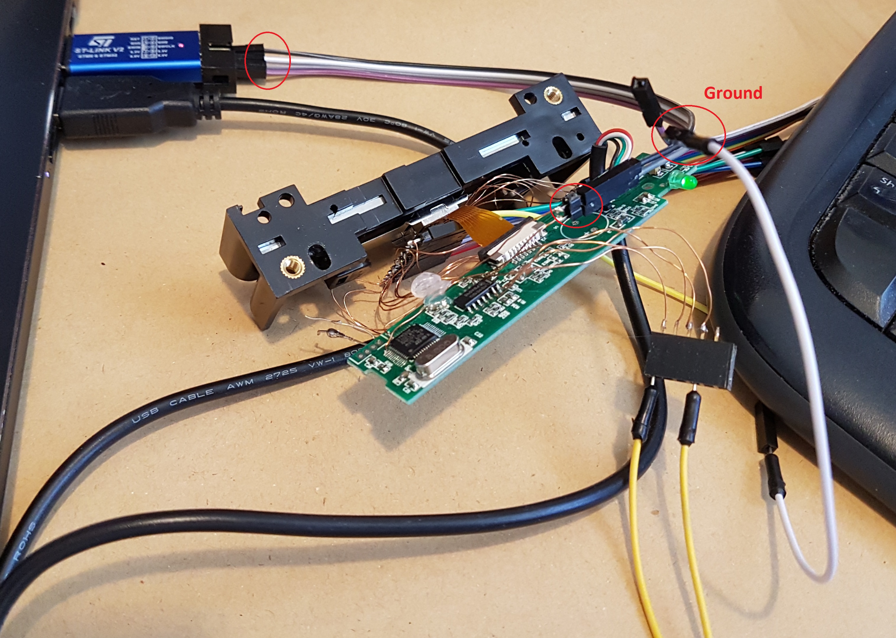
Relevant connections highlighted between ST-Link and target
Now we just need to load up the software and connect using the button shown below:
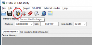
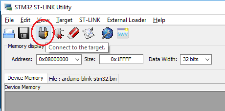
Connect button
Then we can read the firmware. I tweaked the start address and length to values that seemed to get me the whole firmware. The start address can be either 0×00000000 or 0×8000000:
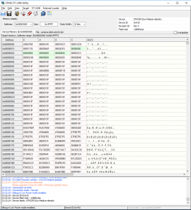
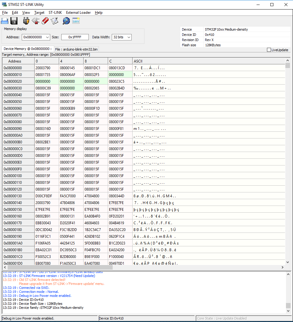
Successful firmware read
To save to a file (always good to have a backup), use the button shown:
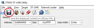
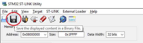
Save firmware to a .bin File
Once the file has been saved, it can be written back using the “Program Verify” button:
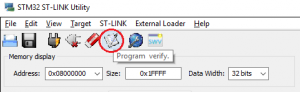

Button to program target with a local .bin File
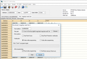
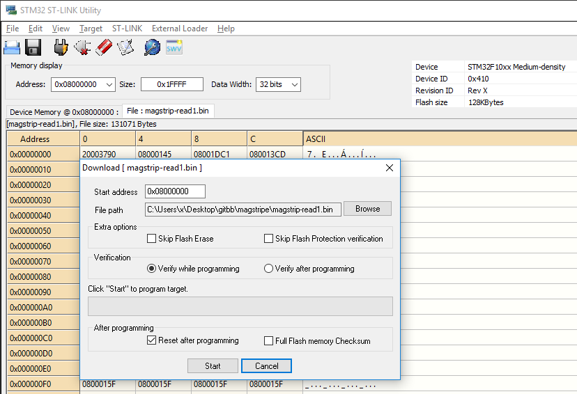
Programming options
After writing, I reset the magstripe reader to check it still worked. It did.
So, with very little effort we were able to read and write firmware to the device.
Conclusion
YouTube videos can be educational as well as fun. Sometimes, reading the firmware can be a lot easier than you’d ever expect. Checking if pins are active using only an oscilloscope wasn’t appropriate in this instance. We actually needed to try communicating with the device.
Where next?
If I was minded to create something rather than to take things apart all the time, I’d probably connect the STM32 to my Arduino software and see if I could write a sketch to read the input pins that connect to the magnetic read heads (via the op amps). Then I’d figure out to do HID emulation (as the original firmware did) so I could read arbitrary magstripes rather than just payment cards.
I got as far as tracing out the 3 input pins using the continuity testing feature on my multimeter.
I was also interested to know if I could have figured out the input pins from looking at the firmware. I loaded up the firmware in Hopper – which was surprisingly easy. But haven’t yet understood it to the extent where I could figure out input pins used. Apparently the assembler code to read of each pin is pretty distinctive, so this certainly seems possible to search for – once you’ve understood the datasheet enough to know what to search for exactly. Checkout 4m30s onwards in this LiveOverflow YouTube video.
It might be possible to write some nefarious firmware that seems to operate as normal, but secretly logs card numbers to the internal flash. Alternatively, maybe it just waits until midnight before it plays a load of malicious keystrokes to the host computer. Or maybe it only plays malicious keystrokes out when an attacker’s creditcard is swiped.
You might want to check out the stm32duino / Blue Pill, which uses the same family of microprocessors and the Pill Duck project which is essentially a USB Rubber Ducky type device that uses the Blue Pill hardware. Take care when Googling for blue pills, though.